MFTK-MM850-SM1310

£1,417.03

Weekly rental:

£1,417.03

Monthly rental:

£3,036.49

Fixed Weekly Rental charges for 1 – 7 days. Fixed Monthly Rental Charges for 8 -30 days. Any days above 30 days will be charged at AED 500/day.

Multifiber Pro Kit With 850/1310 NM PMLS

Pickup Date & Time
Drop-off Date & Time

Description

MultiFiber™ Pro Optical Power Meter and Fiber Test Kits

Introducing the MultiFiber™ Pro Optical Power Meter and Fiber Test Kits. 
MultiFiber Pro Optical Power Meter and Source is the only fiber tester that can certify MPO fiber trunks without the use of fan-out  cords. This singlemode and multimode MPO fiber testing kit eliminates the complexity of polarity issues, and it makes cassettes easier to test in the field. Whether it is using 10 Gbps preterminated MPO fiber trunks or planning for next-generation 40/100 Gbps Ethernet performance, data centers are standardizing on an MPO connector solution. Typical data center fiber installation means time-consuming, manual and imprecise MPO validation. MultiFiber Pro Optical Power Meter and Source is 90 percent faster than single fiber cable certification because it measures power loss and validates polarity on 12 fibers in a single connector— reducing test time from weeks to days.

MultiFiber Pro Optical Power Meter

First MPO fiber tester to support both Singlemode and Multimode MPO fiber certification

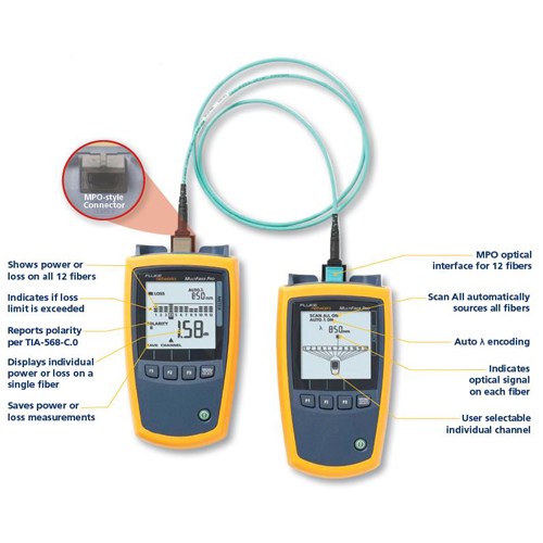
  1. Automatic scanning and testing of all fibers in MPO connectors with “Scan All”
  2. Support for both Multimode and Singlemode MPO fiber trunks
  3. Eliminates the need for fan-out cords when testing MPO fiber trunks
  4. Easy to interpret test results with minimal navigation
  5. The user interface displays all 12 fibers
  6. Automatic 8, 10 and 12 fiber measurements
  7. Troubleshoot MPO fiber links and drill down to single fiber test results

Features

“Scan All” Function

The Scan All function in the MultiFiber Pro Power Meter automatically scans and tests all 12 fibers in MPO connectors – taking just 6 seconds to complete all loss or power measurements. This feature automates the certification of MPO terminated fibers and eliminates the time consuming and manual process of moving the fiber tester from fiber to fiber while using fan-out cords.


Built-in Polarity Verification

The simple purpose of any polarity scheme is to provide a continuous connection from the link’s transmitter to the link’s receiver. For array connectors, TIA-568-C.0 defines three methods to accomplish this: Methods A, B and C. Deployment mistakes are common because these methods require a combination of patch cords with different polarity types. The polarity measurement of MultiFiber Pro allows the user to test individual patch cords, permanent links and channels for correct polarity.

Polarity Measurement of MultiFiber Pro


On-board MPO Connector

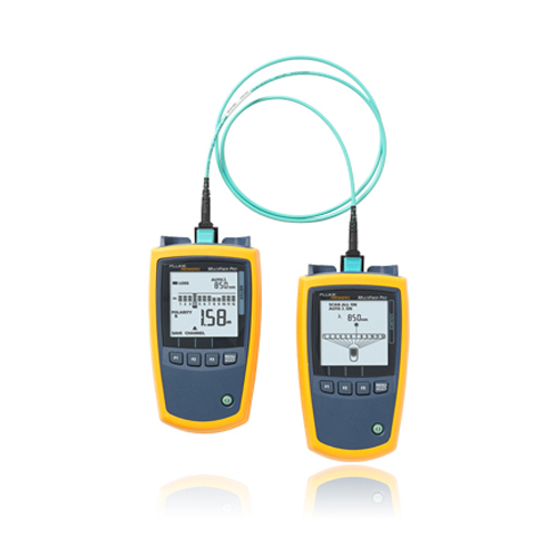
Equipped with MPO connector on both the Optical Power Meter and Light Source, it eliminates the use of costly and complicated fan-out cords to test MPO fibers.

 MPO connector on MultiFiber Pro eliminates the use fan-out cords

Uncovered ports can put cabling, equipment and testers at risk for contamination and affect performance. Ensuring a covered connection on your tester can protect it from dirt and dust. MultiFiber Pro makes it easy by shuttering the MPO connector giving you greater test reliability and peace of mind.

Simple User Interface

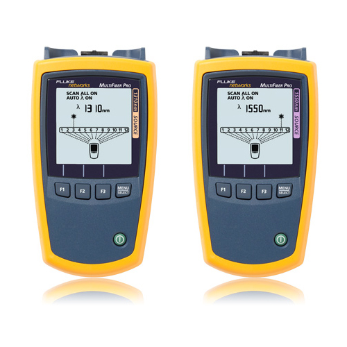
The MultiFiber Pro is so successful at simplifying the task of simultaneously representing polarity, power and loss results for 12 fibers that the user interface is patent pending. The power meter enables the users to easily comprehend the measurement results of 12 fibers simultaneously. The light source identifies each fiber within the MPO connector that is being tested. Any individual measurement that fails the test limit is plainly identified to allow root-cause analysis. This powerful yet straightforward test set enables everyone to become a fiber testing expert and increases efficiency in testing data center projects.

 
Select an Individual Fiber

One of the main problems in the data center is the ability to drill down to a single fiber during testing and troubleshooting. MultiFiber Pro can troubleshoot a single fiber within an MPO trunk and provide a single fiber test result. This ability increases MPO connector verification and troubleshooting flexibility with more precise, per-fiber data and reporting.

Easy Reporting

The MultiFiber Pro Power Meter stores up to 3,000 test results (or the equivalent of 250 MPO cables) internally which can be uploaded to a PC using the LinkWare™ 7 Cable Test Management Software. LinkWare 7 allows you to manage test results, edit cable ID’s, print professional reports and even export the data into spreadsheet formats.

LinkWare PC Cable Test Management Software Reports

Kits for Every Need

MultiFiber Pro is available in several convenient kit configurations to meet all your cleaning, inspection and verification testing needs. Some kits include:

FI-7000 FiberInspector Pro with MPO tip and cleaning supplies
The FI-7000 is the ultimate inspection tool. It enables you to quickly inspect and certify fiber end-faces inside ports or patch cords. It’s 2-second automated PASS/FAIL eliminates human subjectivity and enables anyone to become a fiber inspection expert.

  1. Automated Pass/Fail acceptance testing of fiber end-faces
  2. Large touchscreen for pinch and zoom
  3. Graphical indication of problem areas due to contamination, pits, chips, and scratches
  4. Certify to industry standards – IEC 61300-3-35
  5. Eliminate human subjectivity from end-face measurements
  6. Includes MPO tip for inspection probe and MPO cleaner

FI-7000 FiberInspector Pro with MPO tip

Fiber Cleaning – Quick Clean™ Cleaners
Cleaning is critical. Fluke Networks’ Quick Clean Cleaners instantly clean fiber optic bulkhead connectors and end-faces. Just push the tool tip to engage cleaning action and pull back on the wheel – it’s that simple. The MPO Quick Clean Cleaner is bundled with the MultiFiber Pro kits to ensure that you have the best cleaning tool from the beginning.

Fiber Cleaning - Quick Clean Cleaners

Specifications

Environmental        
Operating temperature -10ºC to +50ºC
Storage temperature -20ºC to +50ºC
Operating humidity 95% (10ºC to +35ºC) non-condensing
75% (35ºC to +45ºC) non-condensing
Uncontrolled <10ºC
Operating altitude 4,000 m
Storage altitude 12,000 m
Vibration Random 2 G, 5 Hz to 500 Hz


Optical Power Meter (Specifications apply at 23ºC (73ºF), unless otherwise noted.)
Detector type InGaAs
Calibrated wavelengths 850 nm, 1300 nm, 1310 nm, 1550 nm
Measurement range 0 dBm to -50 dBm
Test time 6 seconds
Power measurement linearity ±0.1 dB2
Power measurement uncertainty ±0.35 dB2
Power measurement repeatability < 0.10 dB2
Display resolution, dB or dBm 0.01
Power display units dBm, mW, µW
User-selectable limit for loss 0.05 dB to 50.0 dB, in increments of 0.05 dB up to 10.0 dB and 0.1 dB up to 50.0dB
Auto wavelength detection Yes
Polarity detection Detects A, B, C, and Corning Plug & Play™ Universal Systems polarities
2 kHz detection Yes
Record storage 3000 records, one fiber per record (250 12-fiber cables)
External interface USB 2.0, full speed
Optical connector MPO interface for 12-fiber, unpinned plugs. Compatible with 62.5 µm, 50 µm, and singlemode fibers. Connector has a self-closing, protective cover.
Power requirement 2 AA alkaline batteries
Battery life3 30 hours (typical)
Automatic power-off 10, 20, 30, or 60 minutes (can be disabled by the user)
Low battery warning Low battery icon blinks
Size 5.8 in x 3.2 in x 1.6 in (14.7 cm x 8.0 cm x 4.0 cm)
Weight 10.9 oz (309 g)
  1. For 850 nm, 0 dBm to -50 dBm. For 1300, 1310, 1550 nm, -5 dBm to -50 dBm
  2. For a continuous-wave optical signal.
  3. Measured power levels≤ 0 dBm. Backlight on. Battery life depends on the condition and type of batteries used. Fluke Networks recommends alkaline batteries.
  4. 23°C, after 10 minutes of warm-up time.
  5. 23°C, after 15 minutes of warm-up time.
  6. Auto wavelength, SCAN ALL, and backlight on. Battery life depends on the condition and type of batteries used. Fluke Networks recommends alkaline batteries.


Sources

  850 nm Source 1310 nm Source 1550 nm Source
Emitter type LED Laser
Wavelength ±30 nm 1310 nm ±20 nm 1550 nm ±20 nm
Spectral width (FWHM) 50 nm (typical) 2 nm typical, 5 nm maximum
Minimum output power ≥ -24 dBm ≥ -1 dBm
Power output stability ≤±0.1 dB over 8 hours4 ±0.25 dB over 8 hours5
Laser safety IEC 60825-1:Class 1
Encircled flux Meets TIA 455-526-14B, ISO/IEC 14763-3, and IEC 61280-4-1 for 50/125 µm at the source’s optical connector. NA
Optical connector MTP/MPO interface for 12-fiber, unpinned plugs. Compatible with 62.5 µm and 50 µm fibers, non-APC only. Connector has a self-closing, protective cover. MTP/MPO interface for 12-fiber, unpinned plugs. Compatible with 9 µm fibers, APC only. Connector has a self-closing, protective cover.
4. 23°C, after 10 minutes of warm-up time.

5. 23°C, after 15 minutes of warm-up time

Modes 2 kHz modulated, auto wavelength/td>
Power requirement 2 AA alkaline batteries
Battery life6 >30 hours (typical)
Automatic power-off 10, 20, 30, or 60 minutes (can be disabled by the user)
Low battery warning Low battery icon blinks
Size 5.8 in x 3.2 in x 1.6 in (14.7 cm x 8.0 cm x 4.0 cm)
Weight 11.4 oz (323 g)


Includes:

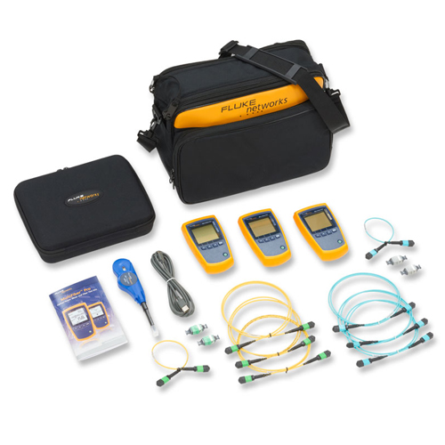
MultiFiber Pro Multimode & 1310 nm Singlemode Kit includes MultiFiber Pro Power Meter, 850 nm Light Source, 1310 nm Light Source, Test Reference Cords, MPO adapters, and carrying case. 

Product Video

Reviews

There are no reviews yet.

Be the first to review “MFTK-MM850-SM1310”

Your email address will not be published. Required fields are marked *

20 − eleven =

clear formPost comment